


MantaRay便携式区域 – 速度流量计
- 测量部分填充管道和明渠中的流量
- 不需要水槽或堰
- 4-20mA和继电器输出,用于连接采样器和SCADA
- 内置可充电镍氢电池供电
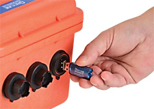
- 200万点数据记录器,USB输出到闪存驱动器
- 背光LCD显示屏,用于流量,累加器和菜单系统
MantaRay Portable Area-Velocity Flow Meter
- Measures flow in partially filled pipes and open channels
- No flume or weir required
- 4-20mA and Relay outputs for connection to Samplers and SCADA
- Powered with built-in rechargeable NiMH batteries
- 2 million point data logger with USB output to Flash drives
- Backlit LCD display for flow rate, totalizer and menu system
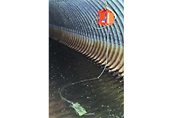
MantaRay便携式区域 – 速度流量计使用超声波传感器测量开放通道,部分填充和附加管道中的流量。它为监测雨水,污水,工业废水,灌溉水和天然溪流而设计。MantaRay显示和数据记录流量和总流量,并连接到采样器,SCADA和遥测系统。
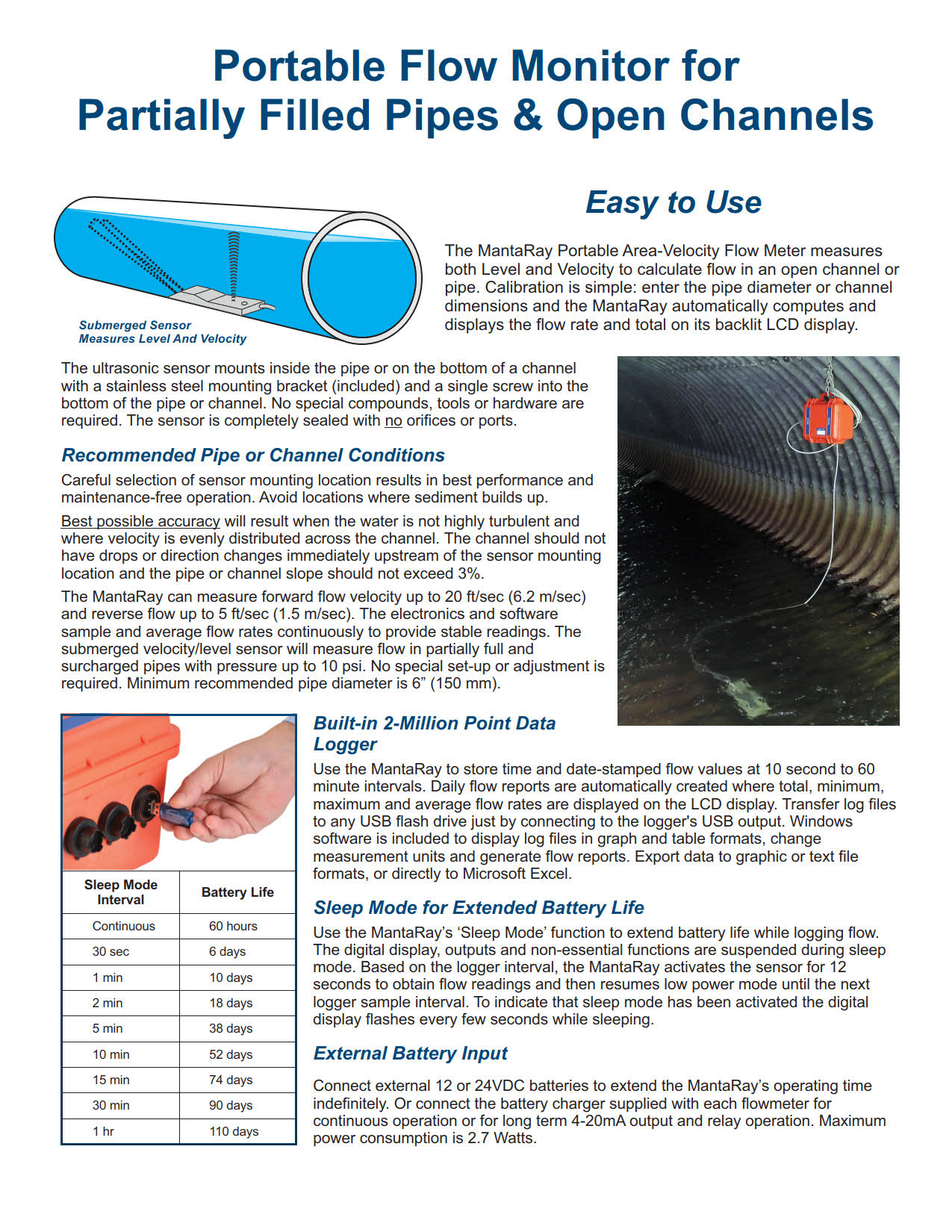
校准很简单:输入管道直径或通道尺寸,MantaRay自动计算并显示其背光LCD显示屏上的流量和总量。将传感器安装在管道或通道的底部,并将IP67电子外壳悬挂在高水位之上。
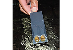
流体动力学超声波传感器
MantaRay使用浸没式超声波传感器连续测量明渠,部分填充或附加管道中的流量或逆流。传感器是密封的超声波单元,没有孔口或端口。它具有流体动力学形状,设计用于排放沉积物和桁条,以便在污水,雨水和溪流应用中可靠运行。
QZ02L传感器安装在管道内或开放通道的底部。不需要特殊的化合物,工具或硬件。包括一个不锈钢安装支架,尺寸范围的可选管带可用于安装在检修孔中的传感器。
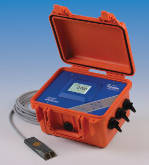
The MantaRay Portable Area-Velocity Flow Meter measures flow in open channels, partially filled and surcharged pipes using an ultrasonic sensor. It’s designed for monitoring stormwater, sewage, industrial effluent, irrigation water and natural streams. The MantaRay displays and datalogs flow rate and total flow and connects to samplers, SCADA and telemetry systems.
Calibration is simple: enter the pipe diameter or channel dimensions and the MantaRay automatically computes and displays the flow rate and total on its backlit LCD display. Mount the sensor at the bottom of the pipe or channel and hang the IP67 electronics case above the high water level.
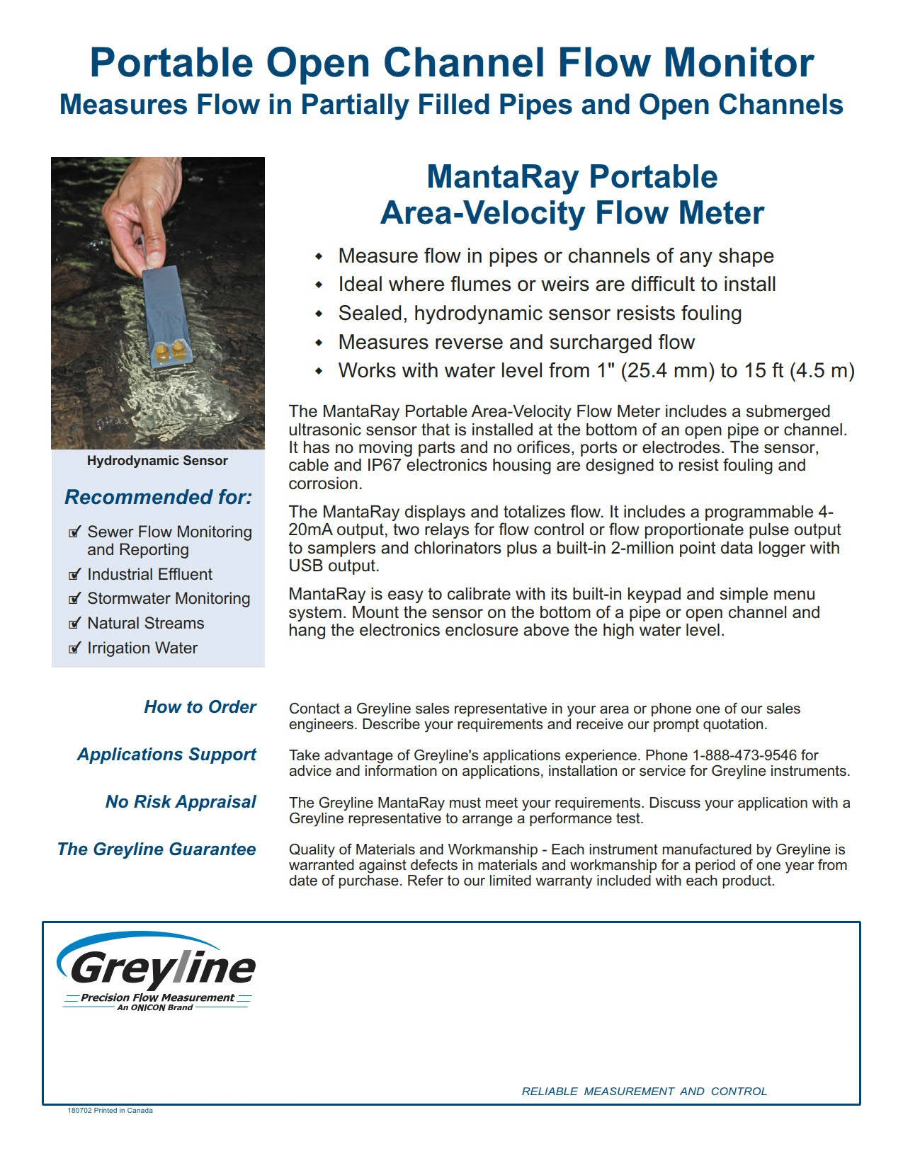
Hydrodynamic Ultrasonic Sensor
The MantaRay uses a submerged ultrasonic sensor to continuously measure flow or reverse flow in open channels, partially filled or surcharged pipes. The sensor is a completely sealed ultrasonic unit with no orifices or ports. It is hydrodynamically shaped and designed to shed deposits and stringers for reliable operation in sewage, stormwater and stream flow applications.
The QZ02L sensor mounts inside the pipe or at the bottom of an open channel. No special compounds, tools or hardware are required. A stainless steel mounting bracket is included and a size range of optional pipe bands are available for sensor installation in manholes.
便携式区域流速监测仪规范
范围:本规范包括一个便携式超声波区域流速监测仪,由Greyline Instruments,Largo,Florida/Long Sault,Ontario制造。
电池供电的仪表应提供通过部分充满或充满电的圆管和矩形、梯形、蛋形或不规则形状的明渠指示、传输和合计流量的功能。
A.通用
流量监测器包括一个潜水超声波传感器、连接电缆和聚碳酸酯外壳,带有指示、数据记录、传输和控制电子设备。
系统应无活动部件。
液位测量精度应为量程的±0.25%。
速度测量精度应为读数的±2%。
B.传感器
超声波传感器的额定值应为IP68,用于连续浸入液体中。
利用多普勒原理,传感器应测量0.1至20 ft/sec(0.03至6.2 m/sec)的流体速度,并反向流动至-5 ft/sec(-1.5 m/sec)。
利用超声波回声测距原理,水下传感器应测量1“至15 ft.(25.4 m m至4.57 m)的液位。
液位传感电路应包括用于自动温度补偿的温度传感器。
传感器应由316不锈钢和环氧树脂制成。
传感器工作温度应为5°F至150°F(-15°C至65°C)。
应包括制造商推荐的不锈钢传感器安装支架。
C.传感器连接电缆
提供25英尺(7.6米)长的三同轴屏蔽电缆,并将其封装在传感器头上。
传感器电缆和连接插头应防水。
外露材料应仅为聚氨酯。
D.电子
流量计应由内部可再充电的12Vdc镍氢电池供电,电池容量为10000 mAh,最大功耗为2.7瓦特。
流量计电子设备应安装在防水、密封、防尘的IP67手提箱中,带可锁铰链盖。
提供一个白色背光矩阵液晶显示器,以用户选择的工程单位显示流量、液位、速度、继电器状态和14位积算器。
便携式流量计应能对任何形状的圆管和明渠进行现场校准。
应通过内置5键校准系统进行校准,并选择参数菜单。校准数据应具有密码保护。
不接受通过参数代码、BCD开关或外部校准器进行校准的系统。
现场校准应允许选择和自动转换测量单位、测量范围、高/低流量报警继电器和流量比例继电器脉冲速率。
流量计应允许现场可编程阻尼在湍流条件下平稳输出。
流量计的工作温度应为-5°至140°F(-20°至60°C)。
流量计应具有菜单选择的4-20mA输出,额定值为500欧姆,0-5Vdc,额定值为100 mA。
提供两个固态继电器,最大40V AC/DC,额定值为250 mA,最大频率为0.4 Hz。
继电器应可由操作员编程,用于与远程累加器或取样器的流量比例脉冲、高低流量、速度和/或液位报警、回波损失报警。
流量计应包括一个外部接线盒,用于辅助连接,包括继电器、模拟输出和电源输入。
流量计应包括一个内置的200万点数据记录器,具有到闪存驱动器或大容量存储设备的USB输出。
记录器不需要连接到笔记本电脑或PC进行数据下载。
数据记录器应支持时间和日期标记日志记录,并生成格式化的流量报告,包括可在流量计显示屏上查看的总流量、平均流量、最小流量、最大流量和发生次数。
E.PC软件
应包括Windows软件,用于从水平速度记录器中检索、显示、保存和导出日志文件。
应支持Windows版本,包括XP、Vista、7和8。
应显示、保存、输出到打印机,并以图形和表格格式导出日志文件。导出的日志文件应进行分隔,以便导入Excel电子表格或数据库程序。
应允许线性和体积单位的转换。
F.根据需要插入的可选功能
应包括50 ft/15 m长的传感器电缆延长线和水密连接器插头,以允许传感器安装与电子外壳之间的总距离为75 ft/23 m。
电缆延长线应采用耐用聚氨酯涂层进行屏蔽、潜水。
G.制造商
便携式区域流速监测仪应为Greyline生产,并保证一年内不会出现材料和工艺缺陷。
规格如有更改,恕不另行通知。如果您需要更多信息或申请中的建议,请联系Greyline。我们可以提供报价,并向贵公司所在地区的Greyline销售代表咨询。
PORTABLE AREA-VELOCITY FLOW MONITOR SPECIFICATIONS
SCOPE: This specification covers a portable, ultrasonic area-velocity flow monitor as manufactured by Greyline Instruments, Largo, Florida / Long Sault, Ontario. The battery-powered instrument shall provide for indicating, transmitting, totalizing of the flow rate through partially filled or surcharged round pipes and rectangular, trapezoidal, egg or irregular shaped open channels.
A. GENERAL
Flow Monitor to consist of a submersible ultrasonic sensor, connecting cable, and polycarbonate enclosure with indicating, data logging, transmitting and controlling electronics. The system shall have no moving parts.
Level measurement accuracy shall be ±0.25% of Range. Velocity measurement accuracy shall be ±2% of reading.
B. TRANSDUCER (SENSORS)
Ultrasonic sensor shall be rated IP68 for continuous submersion in liquids.
Using the Doppler principle, the sensor shall measure fluid velocities from 0.1 to 20 ft/sec (0.03 to 6.2 m/sec) and reverse flow to -5 ft/sec (-1.5 m/sec).
Using ultrasonic echo-ranging principle, the submerged sensor shall measure liquid level from 1″ to 15 ft. (25.4 mm to 4.57 m).
Level sensing circuitry shall include a temperature sensor for automatic temperature compensation.
Sensor shall be constructed of 316 stainless steel and epoxy resin.
Sensor operating temperature shall be 5°F to 150°F (-15°C to 65°C).
Shall include manufacturer’s recommended stainless steel sensor mounting bracket.
C. SENSOR CONNECTING CABLE
Provide 25 ft (7.6 m) length tri-coaxial shielded cable with potted bond to the Sensor head. Sensor cable and connection plug shall be waterproof. Exposed material shall be polyurethane only.
D. ELECTRONICS
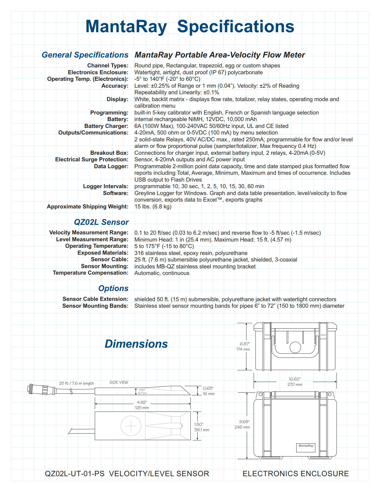
The flow meter shall be powered by internal, rechargeable 12VDC NiMH batteries with 10,000 mAh capacity and maximum power consumption of 2.7 Watts.
Flow meter electronics shall be housed in a watertight, airtight, dust proof IP67 carry case with lockable, hinged cover.
Provide a white, backlit matrix LCD display indicating flow rate, level, velocity, relay states and 14-digit totalizer in user-selected engineering units.
The portable flow meter shall provide for field calibration to round pipes and open channels of any shape.
Calibration shall be via built-in 5-key calibration system with menu selection of parameters. Calibration data shall be password protected. Systems requiring calibration by Parameter codes, BCD switches or external calibrators shall not be accepted.
Field calibration shall allow selection and automatic conversion of measurement units, measurement span, high/low flow alarm relay and flow proportional relay pulse rates.
Flow meter shall permit field programmable damping to smooth output in turbulent flow conditions.
Flow meter operating temperature shall be from -5° to 140°F (-20° to 60°C).
Flow meter shall have menu-selectable 4-20mA output rated 500 ohms and 0-5VDC rated 100 mA.
Provide two solid-state relays, 40V AC/DC max., rated 250mA with maximum frequency of 0.4 Hz. Relays shall be operator-programmable for flow proportionate pulse to a remote totalizer or sampler, high-low flow, velocity and/or level alarm, echo loss alarm.
The flow meter shall include an external breakout box for ancillary connections including relays, analog outputs and power input.
The flow meter shall include a built-in 2 million point Data Logger with USB output to flash drives or mass storage devices. The logger shall not require connection to a laptop or PC for data download. The data logger shall support time and date-stamped logging and generate formatted flow reports including total, average, minimum, maximum and times of occurrence which can be viewed on the flow meter display.
E. PC SOFTWARE
Shall include Windows software to retrieve, display, save and export log files from the Level-Velocity Logger. Shall support Windows versions including XP, Vista, 7 and 8.
Shall display, save, output to a printer and export log files in graph and tabular format. Exported log files shall be delimited for import to Excel spreadsheet or database programs.
Shall permit conversion of linear and volume units.
F. OPTIONAL FEATURES FOR INSERTION AS REQUIRED
Shall include 50 ft / 15 m length sensor cable extension with watertight connector plugs to permit sensor installation total distance of 75 ft / 23 m from the electronics enclosure. Cable extension shall be shielded, submersible with a durable polyurethane coating.
G. MANUFACTURER
Portable Area-Velocity Flow Monitor shall be Greyline MantaRay and warranted against defects in materials and workmanship for one year.
Specifications are subject to change without notice. Please contact Greyline if you need more information or for advice in your application. We can provide quotations and refer you to the Greyline sales representative in your area.
流量计运作原理
仪器电子设备测量从发送声音到回声返回所需的时间。根据空气中的声速,可以高精度计算出液体表面与传感器的准确距离(0.25%范围)。
由于声速受空气温度的影响,灰线超声波液位传感器包括一个内置的温度传感器。水平/距离测量在传感器的整个工作温度范围内自动进行温度补偿。
传感器的位置应使其能清楚地“看到”液体表面,远离梯子、管道或其他障碍物。Greyline建议每10英尺深度距离侧壁1英尺(每3米深度300毫米)。来自搅拌器的假回波(在传感器下扫过)、湍流和波可以被仪器过滤和忽略。
Greyline模型的范围从简单的4-20mA液位指示发送器,到复杂的监控、控制和数据记录模型。返回greyline产品了解级别模型详细信息和规格。有关包括超声波在内的各种液位仪表技术的信息,请参阅废水液位测量技术。
测量管外脏污或充气液体的流量
多普勒效应由奥地利物理学家克里斯蒂安·多普勒于1842年提出。我们每天都能听到多普勒的例子:火车经过时的汽笛声改变音调,或者赛车驶过我们的位置时的排气噪音。
多普勒技术只适用于含有固体或气泡的液体来反射其信号。这些是“困难”的液体,可能会损坏常规流量计:泥浆、污泥、废水、磨料、粘性和腐蚀性化学品。由于传感器安装在管道外部,因此没有压降,也没有流动障碍物。
为了获得很好性能,多普勒传感器应安装在远离湍流产生装置(如弯管和三通)的地方,远离速度增加装置(如控制阀和泵)。典型精度为满刻度的±2%。多普勒仪器包括一个夹式超声波传感器、连接电缆和一个电子外壳,可以安装在附近方便的位置(500英尺/152米范围内)。传感器可以本质安全地额定安装在危险的额定位置。
需要非常精确的定时电路,但当传感器可以安装在流量均匀分布的管段上时,1%的精度非常典型。
由于超声波信号必须穿过管道到达接收传感器,因此流体中不得含有大量气泡或固体(小于2%)。否则高频声音会减弱,太弱,无法穿过管道。应用包括饮用水、冷却水、水/乙二醇溶液、液压油、燃油和化学品。
渡越时间传感器通常工作在1-2兆赫的频率。高频设计通常用于较小的管道,低频设计用于直径达数米的大型管道。
水槽和堰是专门设计的渠道形状,以表征水流。常见的类型有矩形堰、V型槽堰、Parshall水槽和Palmer Bowlus水槽。水槽或堰型的选择取决于应用:流速、渠道形状和水的固体含量。请联系Greyline Instruments以获取有关为您的应用选择合适水槽或堰的建议。
灰线明渠流量计可以通过菜单选择校准到水槽或堰。明渠流量计电子设备使用内部公式计算流量(流量=k h n,其中“k”和“n”为常数,“h”为仪器测量的压头)。通过直接输入“k”和“n”常数,可以对不常见或自定义水槽进行校准。Greyline还提供了一个PC软件程序“find k&n”,用于根据水槽或堰流图开发校准常数。
Greyline明渠流量计包括非接触式超声波传感器、连接电缆和电子外壳,可安装在附近方便的位置(500 ft/152 m内)。传感器可以本质安全地额定安装在危险的额定位置。仪器显示、汇总、传输和控制,有些型号包括数据记录/流量报告系统。
在没有水槽或堰的情况下测量明渠流量。面积速度流量计连续测量水位和流速,以计算明渠或管道中的流量。
超声波传感器安装在管道或通道的底部。为了测量水位,传感器发送超声波脉冲,这些脉冲通过水传播并从液体表面反射出来。仪器精确测量回声返回传感器所需的时间。根据水中声速,测量声级精度为±0.25%。
用连续注入水中的超声多普勒信号测量流速。这种高频声音(640kHz)从悬浮在液体中的颗粒或气泡反射回传感器。如果流体在运动,回声以与流速成比例的变化频率返回。利用该技术,仪器测量流速的精度为±2%。
greyline面积流速流量计工作在部分满管和溢流管、矩形、梯形和蛋形通道中。
可选-单独的液位和速度传感器
一个单独的向下看超声波传感器可用于高充气或湍流应用。它通过将超声波脉冲通过空气传输到液体表面来测量液位,精度为±0.25%。在水位传感器的基础上,采用水下多普勒速度传感器对水位进行测量。
HOW IT WORKS
The instrument electronics measure the time it takes from transmitted sound to return of the echo. With reference to the speed of sound in air, the exact distance of the liquid surface from the sensor can be calculated with high accuracy (±0.25% of maximum range).
Since the speed of sound is affected by air temperature, Greyline ultrasonic level sensors include a built-in temperature sensor. Level/distance measurements are automatically temperature compensated throughout the operating temperature range of the sensor.
The sensor should be positioned so that it has a clear “view” of the liquid surface and away from ladders, pipes or other obstructions. Greyline recommends 1 ft. from the sidewall for every 10 ft. depth (300 mm for every 3 m depth). False echoes from agitators (sweeping under the sensor), turbulence and waves can be filtered and disregarded by the instrument.
Greyline models range from simple 4-20mA level indicating transmitters, to sophisticated monitoring, controlling and data logging models. Return to Greyline Products for Level model details and specifications. For information on a wide range of level instrument technologies including ultrasonics, read Wastewater Level Measurement Techniques.
Doppler flow meters measure flow from outside a pipe with a clamp-on sensor. Greyline Doppler meters continuously transmit high frequency sound (640 kHz) that travels through the pipe wall and into the flowing liquid. Sound is reflected back to the sensor from solids or bubbles in the fluid. If the fluid is in motion, the echoes return at an altered frequency proportionate to flow velocity. Doppler flow meters continuously measure this frequency shift to calculate flow.
Measure Flow of dirty or aerated Liquids from Outside a Pipe
The Doppler effect was first documented in 1842 by Christian Doppler, an Austrian physicist. We hear everyday examples of Doppler: the sound of a train whistle changing pitch as it passes by, or the exhaust noise from a race car as it speeds past our location.
The Doppler technique only works on liquids which contain solids or gas bubbles to reflect its signal. These are “difficult” liquids that may damage regular flow meters: slurries, sludge, wastewater, abrasives, viscous and corrosive chemicals. Because the sensor mounts on the outside of the pipe, there is no pressure drop and no obstruction to flow.
For best performance Doppler sensors should be mounted away from turbulence creating devices like pipe elbows and tees, and away from velocity increasing devices like controlling valves and pumps. Typical accuracy is ±2% of full scale. Doppler instruments include a clamp-on ultrasonic sensor, connecting cable and an electronics enclosure which can be mounted at a convenient location nearby (within 500 ft / 152 m). Sensors can be rated intrinsically safe for mounting in hazardous-rated locations.
Very accurate timing circuits are required but 1% accuracy is quite typical when the transducers can be mounted on a pipe section with evenly distributed flow.
Because the ultrasonic signal must cross the pipe to a receiving transducer, the fluid must not contain a significant concentration of bubbles or solids (less than 2%). Otherwise the high frequency sound will be attenuated and too weak to traverse the pipe. Applications include potable water, cooling water, water/glycol solutions, hydraulic oil, fuel oils and chemicals.
Transit Time transducers typically operate in the 1-2 MHz frequencies. Higher frequency designs are normally used in smaller pipes and lower frequencies for large pipes up to several meters in diameter.
Flumes and weirs are specially designed channel shapes that characterize the flow of water. Common types are Rectangular Weirs, V-Notch Weirs, Parshall flumes and Palmer Bowlus flumes. The choice of flume or weir type depends on the application: flow rate, channel shape and solids content of the water. Contact Greyline Instruments for advice on selection of a suitable flume or weir for your application.
Greyline open channel flow meters can be calibrated to any flume or weir by menu selection. The open channel flow meter electronics use an internal formula to calculate flow rate (Flow = K Hn, where ‘K’ and ‘n’ are constants and ‘H’ is Head as measured by the instrument). Calibration to uncommon or custom flumes can be done by direct entry of ‘K’ and ‘n’ constants. Greyline also offers a PC software program “Find K&n” to develop calibration constants from a flume or weir flow chart.
Greyline open channel flow meters include a non-contacting ultrasonic sensor, connecting cable and an electronics enclosure which can be mounted at a convenient location nearby (within 500 ft / 152 m). Sensors can be rated intrinsically safe for mounting in hazardous-rated locations. The instruments display, totalize, transmit and control, and some models include data logging/flow reporting systems.
Measure open channel flow without a flume or weir An Area-Velocity Flow Meter continuously measures both Level and Velocity to calculate flow volume in an open channel or pipe.
The ultrasonic sensor is installed at the bottom of a pipe or channel. To measure water level the sensor transmits ultrasonic pulses that travel through the water and reflect off the liquid surface. The instrument precisely measures the time it takes for echoes to return to the sensor. Based on the speed of sound in water, the level is measured with accuracy of ±0.25%.
Flow velocity is measured with an ultrasonic Doppler signal continuously injected into the water. This high frequency sound (640 KHz) is reflected back to the sensor from particles or bubbles suspended in the liquid. If the fluid is in motion, the echoes return at an altered frequency proportionate to flow velocity. With this technique the instrument measures flow velocity with accuracy of ±2%.
Greyline Area-Velocity Flow Meters work in partially full and surcharged pipes, rectangular, trapezoid and egg-shaped channels.
Optional – Separate Level and Velocity Sensors
A separate down-looking ultrasonic sensor can be used for highly aerated or turbulent flow applications. It measures level by transmitting ultrasonic pulses through the air to the liquid surface with accuracy of ±0.25%. Along with the level sensor, a submerged Doppler velocity sensor is used to measure the water velocity.


