


VLF-65E
High Performance Portable VLF Hipot
Features and Benefits
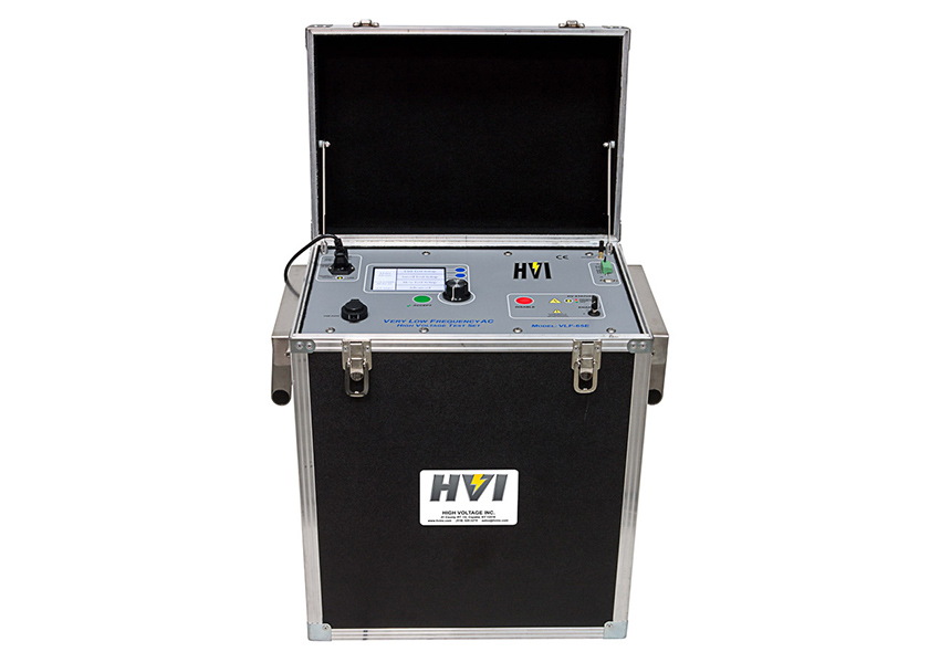
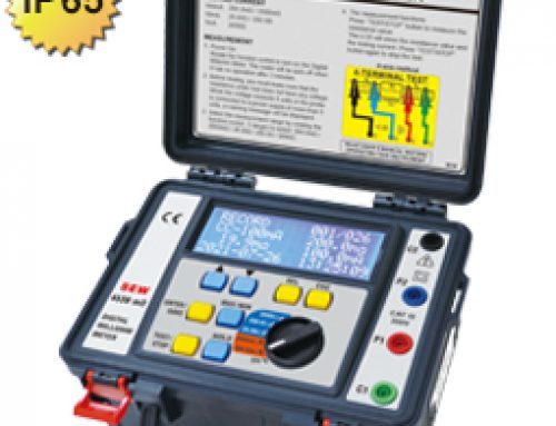
TheVLF-65Eis a top performer from the latest generation of HVI VLF AC hipots using a air-cooled, solid state design with microprocessor control. Test programming, data retrieval, and custom PC software are intuitive and easy to learn. This unit is portable, affordable, and designed to withstand years of field use.
Its 0 – 65 kV AC peak/0 – 46 kV AC RMS output voltage meets world standards for acceptance testing up to 35 kV class cable, and its sine wave output pairs easily with optionaltan deltaandpartial dischargemeasurement systems.
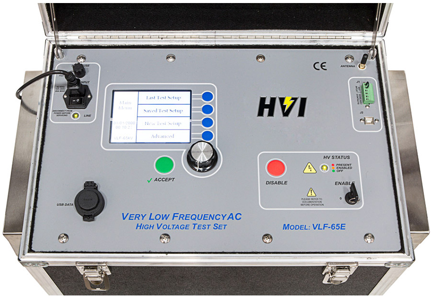
Features:
- VLF and DC output
- Programmable test sequences
- Automatic & manual control
- USB port for exporting data
- Wireless computer interface for remote control operation and data uploadOnscreen tan delta data display with optional TD-65E
- XBee wireless for better signal sustainability and broader range than Bluetooth
Specifications
The VLF-65E meets the following specifications: IEEE 400.2, IEEE 400, IEC 60060-3, CENELEC HD 620/621, VDE DIN 0276-620/621. IEEE 433 for motors/generators.
| Input: | 100 V AC – 265 V AC, 50 Hz/60 Hz, 20 A max |
|---|---|
| Output: | VLF sinewave: 0 – 65 kV AC peak/46 kV AC RMS @ 28 mA RMS VLF square wave: 0 – 65 kV AC peak @ 22 mA DC: 0 – ± 65 kV @ 22 mA Sheath test – programmable |
| Duty: | Continuous |
| Frequency: | 0.1 Hz to 0.01 Hz in steps of 0.01 Hz |
| Load Rating: | 1.0 μF @ 0.10 Hz @ 65 kV 2.0 μF @ 0.05 Hz @ 65 kV 5.0 μF @ 0.02 Hz @ 65 kV 10.0 μF @ 0.01 Hz @ 65 kV μF rating increases at lower voltages Ex: 1.4 μF @ 0.1 Hz @ 47 kV peak |
| Voltmeter: | Voltage kV peak or RMS, +/-1% accuracy |
| Current Meter: | mA peak or RMS, +/-1% accuracy |
| Calculated: | Capacitance, resistance, tan delta flash overvoltage, time to failure |
| Fault Response: | Smart Fault Management – fault burning or shutdown on fault |
| Reports/Data: | Up to 50 test records can be stored in non-volatile memory or removable USB memory stick |
| PC Interface: | USB and XBee wireless |
| PC Software: | Remote control & test data reporting |
| Size & Weight: (W x D x H) | 22 x 14.5 x 26 in., 150 lb 559 x 369 x 660 mm, 68 kg |
| Output Termination: | 20’/6 m flexible x-ray, ground #2 – 20’/6 m #10 test leads, ground hook, line cords |
VLF-65E
高性能便携式VLF Hipot
特点和优点
VLF-65E是从新一代使用空气冷却,固态设计与微处理器控制HVI VLF AC hipots的表现很好。测试编程,数据检索和自定义PC软件直观易学。该装置便携,价格合理,经设计可承受多年的现场使用。
它的0 – 65 kV AC峰值/ 0 – 46 kV AC RMS输出电压符合高达35 kV级电缆的验收测试的标准,并且其正弦波输出与可选的tanδ和局部放电测量系统轻松配对。
特征:
- VLF和DC输出
- 可编程测试序列
- 自动和手动控制
- USB端口用于导出数据
- 无线计算机接口,用于远程控制操作和数据上传屏幕上的正切tan数据显示,带可选TD-65E
- XBee无线技术比蓝牙技术具有更好的信号可持续性和更广泛的范围
技术指标
VLF-65E符合以下规范:IEEE 400.2,IEEE 400,IEC 60060-3,CENELEC HD 620/621,VDE DIN 0276-620 / 621。电动机/发电机的IEEE 433。
| 输入: | 100 V AC – 265 V AC,50 Hz / 60 Hz,至大20 A |
|---|---|
| 输出: | VLF正弦波:0 – 65 kV AC峰值/ 46 kV AC RMS @ 28 mA RMS VLF方波:0 – 65 kV AC峰值@ 22 mA DC:0 –±65 kV @ 22 mA 护套测试–可编程 |
| 义务: | 连续 |
| 频率: | 0.1 Hz至0.01 Hz,步长为0.01 Hz |
| 额定负荷: | 1.0μF@ 0.10 Hz @ 65 kV 2.0μF@ 0.05 Hz @ 65 kV 5.0μF@ 0.02 Hz @ 65 kV 10.0μF@ 0.01 Hz @ 65 kVμF在较低电压下的额定值增加 例如:1.4μF@ 0.1 Hz @ 47 kV峰值 |
| 电压表 | 电压kV峰值或RMS,精度+/- 1% |
| 电流表: | mA峰值或RMS,+/- 1%精度 |
| 计算得出: | 电容,电阻,正切闪光过电压,故障时间 |
| 故障响应: | 智能故障管理–故障刻录或故障停机 |
| 报告/数据: | 非易失性存储器或可移动USB存储器中至多可以存储50条测试记录 |
| PC接口: | USB和XBee无线 |
| PC软件: | 远程控制和测试数据报告 |
| 尺寸和重量:( 宽x深x高) | 22 x 14.5 x 26英寸,150磅 559 x 369 x 660毫米,68公斤 |
| 输出端接: | 20’/ 6 m柔性X射线,地面#2 – 20’/ 6 m#10测试线,接地钩,电源线 |
VLF E SERIES
Advanced VLF Cable Testing Systems
Features and Benefits
HVI has led the industry in manufacturing the portable and easiest to use VLF test instruments since 1998. The E Series represents the apex of these efforts with the advanced features and high reliability of any cable testing system on the market today. This seriesoffers a digital alternative to the VLF Series for performing AC withstand testing and off-line, elevated voltage insulation diagnostic testing. Rugged and reliable, the E Series makes VLF testing faster and easier than ever before. The two models in this best-selling series operate at 0 – 34 kV AC and 0 – 65 kV AC peak voltage with sinusoidal output.
These versatile test sets offer VLF and DC output, sheath testing, and cable fault burning. No PC is required for VLF or TD testing, but using one enables fullremote control of testing, output, and data upload with HVI’s E-Link software. Both models include a USB port for exporting data, and internal memory can store 100 test records of up to 5 hours each. Data is stored automatically in VLF memory with optional backups to USB and PC.XBee wireless connects all components (including optional HVI tan delta instruments), offering a broader range and better signal sustainabilitythan products equipped with Bluetooth.
The 34E is a new generation VLF AC hipot that uses a solid state design with microprocessor controls. It meets the requirements of applicable standards regarding cable testing up to 25 kV class maintenance testing. Compact and light, this instrument is highly portable and deftly handles cable testing needs while conserving space in your field vehicles. Its sine wave output is suitable for using optional external tan deltaand partial dischargedetection equipment.
The 65E is the new addition to the new generation of VLF AC hipots from HVI. Test programming, output functions, wireless communications, and data retrieval are intuitive and easy to learn. This instrumentis designedfor the rigors of field use, like all HVI products. Its 0 – 65 kV AC output voltage meets world standards for acceptance testing up to 35 kV class cable, and its sine wave output is also suitable for using optional TDand PDmeasurement systems.
Features
- VLF and DC output
- Sheath testing
- Cable fault burning
- No PC required for VLF withstand and TD testing
- VLF and TD communicate wirelessly — program TD test from VLF
- Test data records to internal VLF memory and USB stick
- Remote control of VLF and TD with E-Link PC application and XBee wireless
- Higher connection sustainability — more dependable
- No short distance limitations — test from further away
- Stay warm and dry in your truck while testing
- Works in more signal-sensitive locations
- Advanced data capture and reporting capabilities
- Continuous rolling average of TD results and standard deviation
- 6 test results display at once for comparative analysis
- Use built-in templates or create your own
- Multiple fields for writing test descriptions
- 12 VLF & TD reporting routines
High Voltage, Inc.
90 countries served since 1998
Greatest Model Selection
High Voltages Available
High Power Ratings Delivered
Only VLF Thumper Produced
Rugged oil filled non-electronic design offers extreme reliability and ease of field service if ever necessary
Late solid state, computer controlled wireless designs offered
HVI offers more models and higher voltage models. Models range from 30 kVac – 200 kVac peak, offering from 0.4 μF to 50 μF of load capability. Load ratings shown are at the low frequency.
Original Transformer Based Design
VLF-30CM 0-30 kVac, 0.1 Hz, load rated to 0.4 μF
VLF-4022CM 0-44 kVac, 0.1 Hz – 0.02 Hz, load rated to 5.5 μF
VLF-50CM 0-50 kVac, 0.1 Hz – 0.01 Hz, load rated to 50 μF
VLF-6022CM 0-62 kVac, 0.1 Hz – 0.02 Hz, load rated to 5.5 μF
VLF-65CMF 0-65 kVac, 0.1 Hz – 0.01 Hz, load rated to 22 μF
VLF-90CMF 0-90 kVac, 0.1 Hz – 0.02 Hz, load rated to 2.75 μF
VLF-12011CMF 0-120 kVac, 0.1 Hz – 0.01 Hz, load rated to 5.5 μF
VLF-200CMF 0-200 kVac, 0.1 Hz – 0.02 Hz, load rated to 3.75 μF
VT33 VLF: 0-33kVac, 1.0 uF @ 0.1 Hz
Solid State Computer Controlled Models
VLF-34E 0-34 kVac, 0.1 Hz – 0.01 Hz, load rated to 5.0 μF
VLF-65E 0-65 kVac, 0.1 Hz – 0.01 Hz load rated to 10.0 μF
The HVI VLF technology is protected。
AC testing of Cables, Motors &Generators is now easier than ever.
Since the introduction of the High Voltage, Inc. line of portable and affordable VLF hipots, there is a practical method of AC field testing highly capacitive loads, particularly cables and rotating machinery. High Voltage, Inc. offers a full line of VLF AC Hipots from 30 kVac to 200 kVac with models that can test up to 50 μF of load, cables over 50 miles in length and the large of generators or motors. Use VLF for AC Withstand stress tests and/or as a voltage source for Tan Delta and Partial Discharge Diagnostic Testing.
HVI offers both its original, longproven oil filled power supply models with analog controls and its all new solid state, computer and micro-controlled wireless design. Both have diagnostic accessories available.
SINCE 1998, HVI has produced the economical, rugged, and reliable VLF products available. Our electro-mechanical control and our oil filled HV power supply designs are extremely dependable, and if necessary, more easily field serviced than the electronic designs. The HVI design has a proven record with well over 2000 units in service worldwide.
The HVI VLF design offers with manual, easy to use controls but also sophisticated data collection. Electric utilities and industrials have long recognized the benefit of our technology. HVI knows how to build long lasting field test equipment. HVI now also offers the late in solid state design VLF units that offer many benefits, like automatic programmable control and wireless communications.
All HVI VLF designs produce a sine wave output that meets the requirements of standards, permitting it to be used as a voltage source for Tan Delta and Partial Discharge diagnostic testing.
A sine wave producing VLF is required to perform these tests. Keep all options open by choosing a sine wave design, like the HVI VLF.
Why Buy HVI VLF Products
HVI Design – Portable, Affordable, Rugged, Reliable, & Long Proven
HVI Support & Service – Customer Support, Ship from Stock, Instant Factory Help, Quick Service Turn Around, Repair & Cal. Locations Worldwide, Reps in over 90 countries
What is VLF
VLF stands for Very Low Frequency. A VLF hipot is an AC output high voltage instrument. HVI VLF products provide sinusoidal AC voltage but at 0.1 Hz – 0.01 Hz, compared to the 50/60 Hz output of conventional AC test sets. It is still an AC voltage with sinusoidal polarity reversals every half cycle. The VLF instrument is used to provide a simple go/no-go, or pass/fail, withstand test. Also, VLF instruments can be used as the voltage source for performing off-line Partial Discharge and Tan Delta cable diagnostic testing, both from HVI.
Why VLF
VLF test sets are used to field test high capacitance loads like cables and motors/generators. The lower the frequency of an AC source, the lower the current and power required to apply a voltage to a capacitive load like a cable. At 0.1 Hz, it requires 600 times less power to test a cable than at 60 Hz. The HVI VLF instruments permit users to field test long cables and large generators with a portable and affordable test set. A 100 lb VLF instrument can do the job of a multi-ton 60 Hz AC test set.
Cables should be tested with AC voltage. With the HVI VLF products, it can be done with a practical, economical, and easy to use package.
When and Where Is VLF Used – Cable & Rotating Machinery
The principal use of VLF is testing medium and high voltage shielded power cables.
A long cable may have many microfarads of capacitance. To AC high voltage test this cable requires the use of VLF technology. An AC voltage test is the best way to verify the AC integrity of a cable. If a cable can’t hold 2 – 3 times normal voltage, it is not healthy and an in-service failure is likely. Use the VLF to cause defects to fail during the test. Find the fault, make the repair or replacement, and be left with a better cable. It is especially valuable for verifying a cable after installation or repair: far better than using a DC hipot, 5kV megohmmeter, hot stick adaptor, or soak test, none of which provide meaningful information about a cables ability to withstand several times normal AC voltage.
VLF is also very useful for testing large rotating machinery, since it provides a portable and affordable method of field testing coils
.
Partial Discharge & Tan Delta VLF Cable Diagnostic Testing The VLF hipot alone provides a withstand, or proof test. It can also be used as the voltage source for off-line Partial Discharge and Tan Delta cable diagnostic testing. HVI can serve the needs of the industry for cable and generator testing better.
Benefits of HVI VLF AC Hipots
Portable and affordable
All models feature a true sinewave output
Waveform is independent of load capacitance between 0.01 μF and maximum load
High load ratings available
High voltage models available
Simple and easy operation
AC testing does not degrade good cable insulation
Harmful space charges are not injected into the cable insulation
No traveling waves are generated
BNC scope output for waveform viewing
Rugged and reliable design less prone to failure from transients
Two Design Choices
original, electro-mechanical, transformer designs and the late solid state computer controlled designs vailable from HVI.
Testing Methodology
When VLF Withstand testing cable, the proper test voltage and time duration are critical for the success of the test. A defect that is big enough to be excited by the applied voltage will grow to failure during the test. Lesser defects are not affected. They remain dormant and are not aggravated by the test voltage.
IEEE Guide for Field Testing of Shielded Power Cable Systems Using Very Low Frequency (VLF) (less than 1 Hz) Table 3 – VLF withstand test voltages for sinusoidal and cosine-rectangular waveforms (see note 1)
| WAVEFORM | Cable system rating (phase to phase)[kV] | Installation (phase to ground) | Acceptance (phase to ground) | Maintenance2 (phase to ground) (see Note 2) | |||
| [kV RMS] | [kV PEAK] | [kV RMS] | [kV PEAK] | [kV RMS] | [kV PEAK] | ||
| Sinusoidal | 5 | 9 | 13 | 10 | 14 | 7 | 10 |
| 8 | 11 | 16 | 13 | 18 | 10 | 14 | |
| 15 | 19 | 27 | 21 | 30 | 16 | 22 | |
| 20 | 24 (Note 3) | 34 (Note 3) | 26 | 37 | 20 | 28 | |
| 25 | 29 (Note 3) | 41 (Note 3) | 32 | 45 | 24 (Note 3) | 34 (Note 3) | |
| 28 | 32 | 45 | 36 (Note 3) | 51 (Note 3) | 27 | 38 | |
| 30 | 34 | 48 | 38 | 54 | 29 | 41 | |
| (Note 3) | |||||||
| 35 | 39 | 55 | 44 | 62 | 33 | 47 | |
| 46 | 51 | 72 | 57 | 81 | 43 | 61 | |
| 69 | 75 | 106 | 84 | 119 | 63 | 89 | |
NOTE 1 If the operating voltage is a voltage class lower than the rated voltage of the cable, it is recommended that the maintenance test voltages should be those corresponding to the operating voltage class.
NOTE 2 The maintenance voltage is about 75% of the acceptance test voltage magnitude.
NOTE 3 Some existing test sets have a maximum voltage that is up to 5% below the values listed in the table. These test sets are acceptable to be used. However, there is a risk that the cable may be “undertested” due to a combination of lower test voltage and allowed uncertainty of the measuring circuit.
VLF ac voltage testing methods utilize ac signals at frequencies in the range of 0.01 Hz to 1 Hz. The commonly used, commercially available VLF ac voltage test frequency is 0.1 Hz. VLF ac test voltages with cosine- rectangular and the sinusoidal wave shapes are most commonly used. While other wave shapes are available for testing of cable systems, recommended test voltage levels have not been established.
5.1 General VLF ac Withstand Voltage Testing
5.1.1 VLF ac withstand voltage test parameters
The purpose of a withstand test is to verify the integrity of the cable under test. If the test cable has a defect severe enough at the withstand test voltage, an electrical tree will initiate and grow in the insulation. Inception of an electrical tree and channel growth time are functions of several factors including test voltage, source frequency and amplitude, and the geometry of the defect. For an electrical tree from the tip of a needle in PE insulation in laboratory conditions to completelypenetrate the insulation during the test duration, VLF ac voltage test levels and testing time durations have been established for the two most commonly used test voltage sources, the cosine-rectangular and the sinusoidal wave shapes. However, the time to failure will vary according to the type of insulation such as PE, paper, and rubber. Thus the electrical tree growth rate is not the same for all materials and defects.
The voltage levels (installation and acceptance) are based on the most used, worldwide practices of from less than 2 U0 to 3U0, where U0 is the rated rms phase to ground voltage, for cables rated between 5 kV and 69 kV. The maintenance test level is about 75% of the acceptance test level.
One can reduce the test voltage by another 20% if the voltage is applied for longer times (Bach [B2]; Baur, Mohaupt, and Schlick, [B6]; Krefter [B27]). Evidence (Hernandez-Mejía, et al. [B21]) indicates that increasing the voltage above 3U0 to compensate for reduced test cycles (time) does not replicate performance either on test or in service as compared to the lower voltage, longer time tests.
Table 3 lists voltage levels for VLF withstand testing of shielded power cable systems using cosine-rectangular and sinusoidal waveforms (Bach [B2]; Eager, et al. [B9]; Krefter [B27]; Moh [B28]). For a sinusoidal waveform the rms is 0.707 of the peak value, assuming the harmonic distortion is less than 5%. The rms and peak values of the cosine-rectangular waveform are assumed to be equal.
It should be noted that terminations may need to be added to avoid flashover for installation tests on cables rated above 35 kV.
Regarding the test times:
The recommended minimum testing time for a simple withstand test on aged cable circuits is 30 min at 0.1 Hz (Goodwin, Oetjen, and Peschel [B13]). If a circuit is considered as important, e.g., feeder circuits, then consideration should be given to extending the testing time to 60 min at 0.1 Hz (Hampton, et al. [B19].
The recommended minimum testing time for an installation and/or acceptance withstand test on new cable circuits is 60 min at 0.1 Hz.
A test time within the range 15–30 min may be considered if the monitored characteristic remains stable for at least 15 min and no failure occurs. It should be noted that the recommended test time for a withstand test is 30 min.
Summary: The intent of VLF Withstand Testing is to apply a sufficient test voltage for a long enough time to permit any defect big enough to be excited by the voltage applied to fail within the test duration. If a cable can’t withstand the test voltage, let it fail and make the repair or replacement. If the cable passes, there is a high assurance that the cable should not fail in service for many years.
Diagnostic Testing: If a pass/fail AC Withstand test is not desired, there are several Diagnostic Tests available. Using the VLF as the voltage source, Tangent Delta (δ) measurements and Partial Discharge detection can be performed with accessories available from HVI.
VLF E系列
VLF电缆测试系统
特色和优点
E系列代表了这些努力的高点,具有电缆测试系统的比较先进功能和高可靠性。该系列提供VLF系列的数字替代产品,用于执行交流耐压测试和离线,高压绝缘诊断测试。E系列坚固可靠,使VLF测试比以往更快,更轻松。这个畅销系列中的两个型号在0 – 34 kV AC和0 – 65 kV AC峰值电压下工作,具有正弦输出。
这些多功能测试装置提供VLF和DC输出,护套测试和电缆故障烧录。VLF或TD测试不需要PC,但使用HV可以通过HVI的E-Link软件完全远程控制测试,输出和数据上传。两种型号都包含用于导出数据的USB端口,内部存储器可以存储100个测试记录,每个测试记录最多5个小时。数据自动存储在VLF存储器中,可选备份到USB和PC。XBee无线连接所有组件(包括可选的HVI tan delta仪器),与配备蓝牙的产品相比,可提供更广泛的范围和更好的信号可持续性。
34E是使用固态设计与微处理器控制的新一代VLF AC耐压。它符合适用的标准要求,适用于高达25 kV级维护测试的电缆测试。该仪器结构紧凑,重量轻,便于携带,可灵活处理电缆测试需求,同时节省现场车辆的空间。其正弦波输出适合使用可选的外部tan delta和局部放电检测设备。
65E是新加入到新一代的HVI VLF AC hipots的。测试编程,输出功能,无线通信和数据检索直观且易于学习。与所有HVI产品一样,该仪器为现场使用而设计。其0 – 65 kV交流输出电压符合高达35 kV级电缆验收测试的标准,其正弦波输出也适用于可选的TD和PD测量系统。
特征
- VLF和DC输出
- 护套测试
- 电缆故障烧毁
- VLF承受和TD测试无需PC
- VLF和TD无线通信 – 从VLF进行TD测试
- 测试数据记录到内部VLF存储器和USB记忆棒
- 使用E-LinkPC应用程序和XBee无线远程控制VLF和TD
- 更高的连接可持续性 – 更可靠
- 没有短距离限制 – 从更远的地方进行测试
- 在测试时保持卡车保持温暖和干燥
- 适用于对信号更敏感的位置
- 高级数据捕获和报告功能
- TD结果的连续滚动平均值和标准偏差
- 立即显示6个测试结果用于比较分析
- 使用内置模板或创建自己的模板
- 用于编写测试描述的多个字段
- 12个VLF和TD报告例程
High Voltage, Inc.
自1998年以来服务了90个国家
很棒的模型选择
可用的高电压
提供 高功率额定值
仅生成VLF Thumper
坚固耐油的非电子设计,如有必要,可提供很高的可靠性和现场服务
提供 固态计算机控制无线设计
HVI提供的型号范围为30 kVac – 200 kVac峰值,提供0.4μF至50μF的负载能力。 显示的额定负载处于低频率。
原装变压器设计
VLF-30CM 0-30 kVac,0.1 Hz,额定负载0.4μF
VLF-4022CM 0 -44 kVac ,0.1 Hz – 0.02 Hz,额定负载 5.5μF
VLF-50CM 0-50 kVac,0.1 Hz – 0.01 Hz,额定负载为50μF
VLF-6022CM 0-62 kVac,0.1 Hz – 0.02 Hz,额定负载5.5μF
VLF-65CMF 0-65 kVac,0.1 Hz – 0.01 Hz,额定负载22μF
VLF-90CMF 0-90 kVac,0.1 Hz – 0.02 Hz,额定负载 2.75μF
VLF-12011CMF 0-120 kVac,0.1 Hz – 0.01 Hz,额定负载5.5μF
VLF-200CMF 0-200 kVac,0.1 Hz – 0.02 Hz,额定负载3.75μF
VT33 VLF:0-33kVac,1.0 uF @ 0.1 Hz
固态计算机控制模型
VLF-34E 0-34 kVac,0.1 Hz – 0.01 Hz,额定负载 5.0μF
VLF-65E 0-65 kVac,0.1 Hz – 0.01 Hz负载额定值为10.0μF
电缆,电机和发电机的交流测试现在比以往更容易。
自推出 High Voltage,Inc。系列便携式且价格合理的VLF hipot以来,有一种实用的AC场测试高容性负载的方法,特别是电缆和旋转机械。 High Voltage,Inc。提供从30 kVac到200 kVac的全系列VLF AC Hipot, 其型号可测试高达 50μF 的负载,长度超过50英里的电缆以及发电机或电机。 使用VLF进行AC耐压测试和/或作为Tan Delta和局部放电诊断测试的电压源。
HVI提供的充油电源模型,具有模拟控制和全新的固态,计算机和微控制无线设计。 两者都有诊断配件。
自1998年以来,HVI已经生产出经济,坚固,可靠的VLF产品。 我们的机电控制和我们的充油高压电源设计比较可靠,如有必要,比电子设计更容易现场维修。
HVI VLF设计提供的一切,手动,易于使用的控制,但也提供复杂的数据收集。 电力公用事业和工业很早就认识到 了我们技术的优势。 HVI知道如何构建持久的现场测试设备。 HVI现在还提供固态设计VLF单元,可提供许多优势,如自动可编程控制和无线通信。
所有HVI VLF设计 都符合标准要求的正弦波输出,允许将其用作Tan Delta和局部放电诊断测试的电压源。
产生VLF的正弦波需要进行这些测试。 通过选择正弦波设计(如HVI VLF)来 保持选项的 开放性。
为何购买HVI VLF产品?
HVI设计 – 便携,经济,坚固,可靠,经过长期验证
HVI支持与服务 – 客户支持,库存发货,即时工厂帮助,快速服务 周转,维修和校准。
什么是VLF?
VLF代表极低频率。 VLF高压输出是一种交流输出高压仪器。HVI VLF产品提供正弦交流电压,但频率为0.1 Hz – 0.01 Hz 。 它仍然是交流电压,每半个周期正弦极性反转。 VLF仪器用于提供简单的通过/不通过或通过/未通过耐受测试。 此外,VLF仪器可用作 电压源,用于执行HVI的离线局部放电和Tan Delta电缆诊断测试。
为何选择VLF?
VLF测试装置用于现场测试高电容负载,如电缆和电动机/发电机。 AC源的频率 越低,将电压施加到像电缆这样的电容性负载所需的电流和功率就越低。 在0.1 Hz时,测试电缆的功率要比60 Hz时低600倍。 HVI VLF仪器允许用户 使用便携且经济实惠的测试装置 对长电缆和大型 发电机 进行现场测试 。 100磅VLF仪器可以完成多吨60 Hz AC测试装置的工作。
电缆应使用交流电压进行测试。 使用HVI VLF产品,可以使用实用,经济且易于使用的包装 。
何时何地使用VLF – 电缆和旋转机械
VLF的主要用途是测试中高压屏蔽电力电缆。
长电缆可能具有许多微法的电容。 对于交流高压测试,该电缆需要使用 VLF技术。 交流电压测试是验证电缆交流完整性的好方法。 如果电缆不能保持正常电压的2-3倍,则它不健康并且可能发生在线故障。 在测试期间使用VLF导致缺陷失败。 找到 故障,进行维修或更换,并留下更好的电缆。 它对于在安装或维修后验证电缆有价值:优于使用DC高压,5kV兆欧表,热棒适配器或浸泡测试,这些都没有 提供有关电缆能够承受正常交流电压几倍的有意义的信息。
VLF对于测试 大型旋转机械 也非常有用 ,因为它提供了便携且经济实惠的现场测试线圈方法。
局部放电和Tan Delta VLF电缆诊断测试单独的VLF高压提供耐受性, 验证测试。 它还可以用作离线局部放电和Tan Delta电缆诊断测试的电压源。 HVI可以满足电缆和发电机测试行业的需求。
HVI VLF AC Hipots的优点
便携且价格实惠
所有型号均具有真正的正弦波输出
波形与0.01μF和负载之间的负载电容无关
可提供额定载荷
可提供电压型号
操作简单方便
交流测试不会降低良好的电缆绝缘性能
有害空间电荷 不会注入电缆绝缘层
不会产生行波
用于波形查看的BNC示波器输出
坚固可靠的设计不易受瞬态故障的影响
两种设计选择
获得的原装,机电,变压器 设计和HVI提供的固态计算机控制设计。
测试方法
当VLF耐受测试电缆时,正确的测试电压和持续时间对于测试的成功至关重要。 在测试期间,由施加的电压引起的 足够大的缺陷 将变得失败。 较小的缺陷不受影响。 它们保持休眠状态,并且不会因测试电压而恶化。
IEEE使用极低频(VLF)(小于1 Hz)的屏蔽电缆系统现场测试指南表3 – 正弦和余弦矩形波形的VLF耐受测试电压(见注1)
| 波形 | 电缆系统额定值 (相位到相位)[kV] | 安装 (相对地) | 承受 (相对地) | 维护2 (相对地) (注2) | |||
| [kV RMS] | [kV PEAK] | [kV RMS] | [kV PEAK] | [kV RMS] | [kV PEAK] | ||
| 正弦曲线 | 5 | 9 | 13 | 10 | 14 | 7 | 10 |
| 8 | 11 | 16 | 13 | 18 | 10 | 14 | |
| 15 | 19 | 27 | 21 | 30 | 16 | 22 | |
| 20 | 24 (注3) | 34 (注3) | 26 | 37 | 20 | 28 | |
| 25 | 29 (注3) | 41 (注3) | 32 | 45 | 24 (注3) | 34 (注3) | |
| 28 | 32 | 45 | 36 (注3) | 51 (注3) | 27 | 38 | |
| 30 | 34 | 48 | 38 | 54 | 29 | 41 | |
| (注3) | |||||||
| 35 | 39 | 55 | 44 | 62 | 33 | 47 | |
| 46 | 51 | 72 | 57 | 81 | 43 | 61 | |
| 69 | 75 | 106 | 84 | 119 | 63 | 89 | |
注1:如果工作 电压是低于电缆额定电压的电压等级,建议维护测试电压应与工作电压等级相对应。
注2:维持电压约为验收试验电压的75% 。
注3:某些现有测试装置的最大电压低于表中列出的值的5%。 可以使用这些测试集。 然而,由于低 测试电压和允许测量电路的不确定性的 组合,存在电缆可能“承受”的风险 。
VLF交流电压测试方法利用频率范围为0.01Hz至1Hz的交流信号。 常用的市售VLF交流电压测试频率为0.1 Hz。 具有余弦矩形和正弦波的 VLF 交流测试电压
波形是常用的。 虽然其他波形可用于测试电缆系统,但尚未建立推荐的测试电压水平。
5.1通用VLF交流耐压测试
5.1.1 VLF交流耐压试验参数
耐受测试的目的是验证被测电缆的完整性。 如果测试电缆在耐受测试电压下具有足够严重的缺陷,则 电气树将在绝缘体中启动并生长。 电树的开始和通道生长时间是几个因素的函数,包括测试电压,源频率和幅度,以及缺陷的几何形状。 对于 实验室条件下PE绝缘针尖 的电气 测量,以便在测试期间穿透绝缘层,已经确定了两种常用的测试电压源的VLF交流电压测试水平和测试持续时间 ,余弦矩形和正弦波形。 但是,失效时间会根据PE,纸张和橡胶等绝缘材料的类型而有所不同。 因此,材料和缺陷的电树生长速率都不相同。
电压电平(安装和接受)是基于来自小于2 U0至3U0,其中U0是额定有效值相的对地电压,电缆额定5千伏和69千伏之间的常用的做法。 维护测试水平约为 验收测试水平的 75 %。
如果施加更长时间的电压,可以将测试电压再降低20%(Bach [B2]; Baur,Mohaupt和Schlick,[B6]; Krefter [B27])。 证据(Hernandez-Mejía等[B21])表明, 与较低电压,较长时间测试相比,将电压增加到3U0以上以补偿减少的测试周期(时间)不会在测试或使用中复制性能。
表3列出了 使用余弦 – 矩形和正弦波形 的屏蔽电缆 系统的 VLF耐受性测试的电压电平 (Bach [B2]; Eager等[B9]; Krefter [B27]; Moh [B28])。 对于正弦波形,假设谐波失真小于5%,均方根值为峰值的0.707。 假设余弦 – 矩形波形 的均方根和峰值 相等。
应该注意的是,可能需要增加端接以避免在额定电压高于35kV的电缆上进行安装测试时发生闪络。
关于测试时间:
对老化电缆电路进行简单耐受试验 的建议测试时间 为0.1 Hz时30分钟(Goodwin,Oetjen和Peschel [B13])。 如果电路被认为是重要的,例如馈线电路,那么应该考虑将测试时间延长到0.1 H z 时的60分钟 (Hampton,et al。[B19]。
建议的新电缆电路安装和/或验收耐受试验的测试时间为60分钟,0.1 Hz。
如果监测到的特性 在至少15分钟内保持稳定并且没有发生故障, 则可以考虑在15-30分钟范围内的测试时间 。 应该注意的是,耐受试验的推荐测试时间是30分钟。
总结:VLF耐受测试的目的是在足够长的时间内施加足够的测试电压,以允许 足够大 的 y缺陷被测试持续时间内施加的失效电压激发。 如果电缆无法承受测试电压,请将其发生故障并进行维修或更换。 如果电缆通过,则可以确保电缆 在使用多年后不会失效。
诊断测试:如果不需要通过/未通过AC耐压测试,可以使用多个诊断测试。 使用VLF作为电压源, 可以 使用HVI提供的附件进行 正切Delta(δ)测量和局部放电检测 。


